
Metal Building Insulation Installation: Roofs, Walls, and Critical Details
Metal building insulation installation must be coordinated with the purlins, girts, metal panels, and any liner system. The selected assembly determines where the insulation is supported, how much compression is expected, and how facing joints and perimeter details are sealed.
Steel buildings commonly use fiberglass blankets laid over framing, insulation fitted within framing cavities, or multilayer systems with a liner and additional insulation. Each method has a different installation sequence. Effective metal building insulation installation depends on maintaining coverage and the specified assembly configuration, particularly where roof and wall insulation meet.
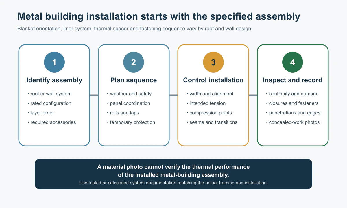
Installation priorities for the selected roof or wall assembly:
- Choose the system first.The roof or wall assembly determines when the insulation is placed relative to the metal panels.
- Control compression.Purlins, girts, and fasteners can reduce installed thickness and form thermal bridges.
- Maintain continuity.Facing laps, penetrations, and perimeter joints must follow the assembly's air, vapor, and weather-control details.
Choose the Installation System First
Product form, framing layout, and envelope design determine the method of metal building insulation installation. Compare the main arrangements before planning material placement and panel work.
| Assembly | Typical installation | Points to check |
|---|---|---|
| Single-layer roof blanket over purlins | Lay faced fiberglass blankets over the purlins before fixing roof panels. | Blanket direction and tension; compression over purlins; facing laps. |
| Roof liner and multilayer system | Fit a liner or support system below the purlins, with insulation between and, where required, above them. | Continuity between layers; supports; vapor control; thermal bridges. |
| Wall blanket over girts | Run blankets across the girts before fitting exterior metal wall panels. | Coverage; compression at girts; facing attachment; perimeter seals. |
| Wall cavity or board system | Fit insulation between girts or install a specified continuous board layer. | Cavity fit; board joints; support or anchorage; openings and corners. |
Single-layer fiberglass blankets provide coverage across repetitive roof and wall areas. Where higher thermal performance is required, the design may include additional layers, liners, or continuous insulation to reduce heat loss at framing interruptions. Before metal building insulation installation begins, select the complete assembly: support, fastening, compression, and sealing details are not interchangeable.
For other assemblies, see Metal Building Insulation.
Installing Insulation on Metal Roofs
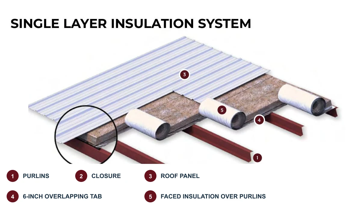
Single-layer blankets draped over purlins
In this arrangement, fiberglass blankets are typically unrolled perpendicular to the purlins, with the facing toward the interior. Roof panels are then installed above the insulation. Follow the specified sequence for the selected metal building insulation installation system.
1. Check the framing and site conditions
Confirm that the purlins, supports, and roof-panel attachment locations match the selected assembly. Keep the blankets dry. Do not unroll them in rain, over standing water, or in winds that prevent safe handling and securing of the material. Coordinate blanket placement with panel installation so large areas are not exposed to weather for extended periods.
2. Unroll and position the fiberglass blanket
Lay each blanket across consecutive purlins in the specified direction. Keep it reasonably smooth and under appropriate tension, without deep wrinkles, excessive sag, or unnecessary stretching. Allow sufficient material at the eaves, ridge, and adjoining runs.
Align faced blankets so the facing laps remain accessible for sealing. Seams that are misplaced during metal building insulation installation may be difficult to close once panels cover the area.
3. Manage compression at purlins
When panels are fastened through the insulation into purlins, local compression can be part of the designed assembly; it is not automatically a workmanship defect. What matters is whether the installed thickness and configuration match the design and achieve the intended thermal performance.
Where thermal spacer blocks are specified, position them to suit the purlins, fasteners, and roof panels. They can reduce the thermal effect of these connections. Extra blanket thickness or excessive tension does not replace the specified assembly detail.
4. Close joints and install roof panels
Bring adjacent insulation edges together without continuous gaps. Seal designated facing laps using a method compatible with the facing and the selected assembly. During panel installation, check that blankets do not shift, fold into connections, or bunch into large compressed areas.
Coordinate fastening with specified spacer blocks, joint treatments, and eave details. Inspect insulation and facing continuity around penetrations before those locations are concealed.
Roof liner and multilayer systems
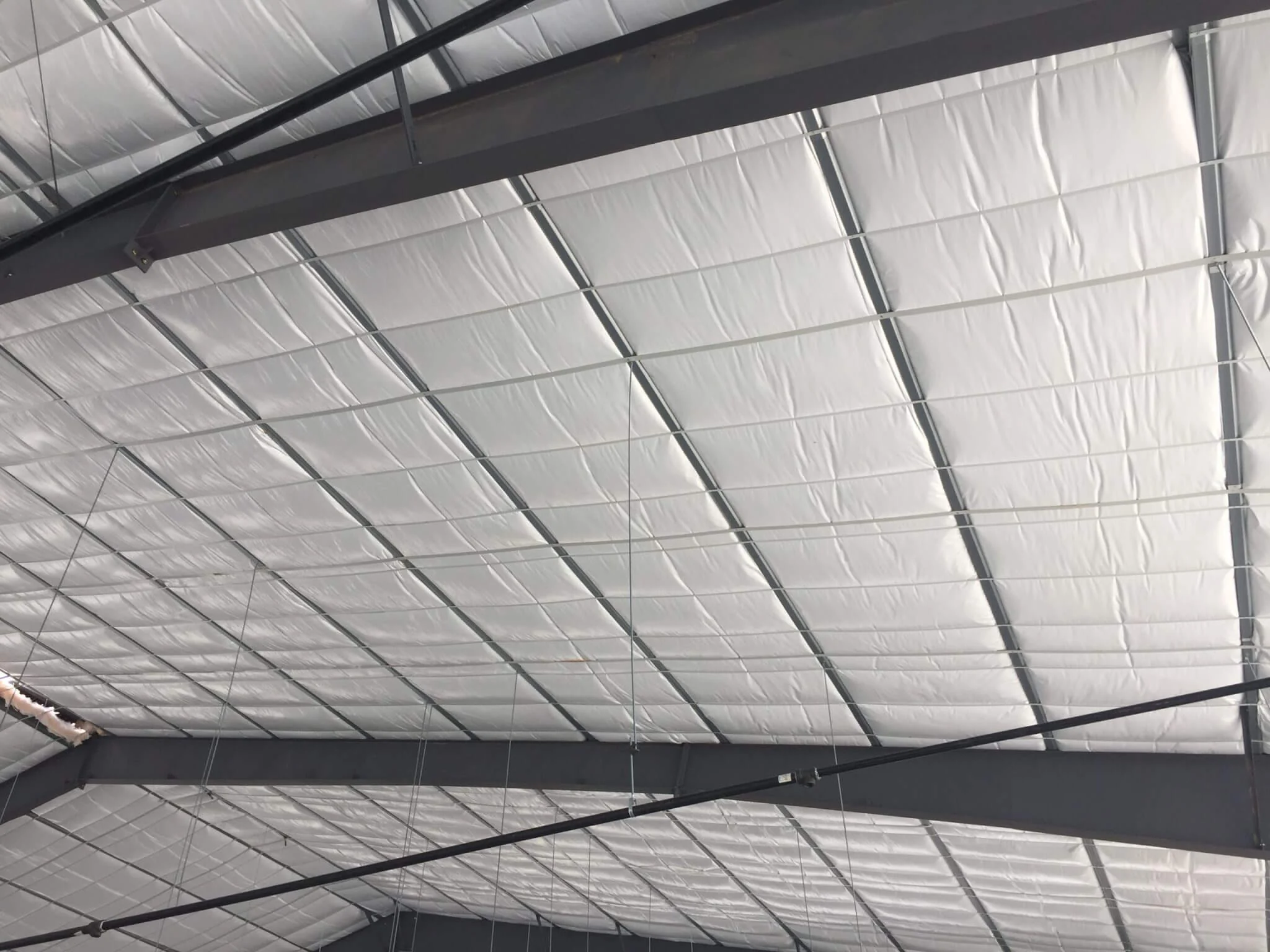
Roof liner systems follow a different sequence. A typical arrangement installs support bands and a continuous liner below the purlins, followed by fiberglass insulation between the purlins and, where required, a second layer above them.
The liner supports insulation and may serve as an interior finish and part of the air- and vapor-control strategy. Fastenings, seams, and perimeter seals must therefore form part of the coordinated design. Multilayer metal building insulation installation must maintain continuity between layers without leaving uninsulated strips or interrupting the intended vapor-control plane.
An additional layer can improve thermal performance where a single-layer roof has compression points. Its facing and support details must suit the complete assembly. Do not introduce another low-permeance layer where a continuous vapor retarder already exists without first checking the moisture-control design.
Installing Insulation on Metal Walls
Wall girts, door and window openings, base edges, corners, and roof-to-wall junctions require coordinated coverage. The method of metal building insulation installation depends on whether blankets cross the girts or insulation is placed within a cavity or liner system.
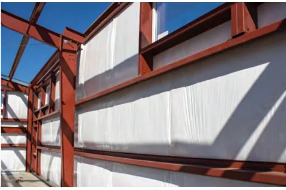
Blankets installed across girts
In an over-girt system, fiberglass blankets are generally positioned outside the girts before exterior metal panels are installed. In common faced fiberglass assemblies, the facing points toward the interior, with designed compression where panels attach to girts.
For this metal building insulation installation method, secure the blankets against downward slipping, sideways movement, and gaps caused by material pulling away from the framing. Close joints and maintain facing continuity at upper and lower edges. Where thermal breaks are specified, use the locations and fixings required by the wall-panel assembly.
Cavity insulation and liner systems
Insulation may instead be placed between girts and held by bands, fasteners, or a liner. Fiberglass should fit the cavity boundaries without continuous gaps. Do not compress an oversized blanket into a shallow cavity or leave uncovered strips because the material is too narrow.
If boards are used, keep joints close and use the designated support or anchorage method. Maintain coverage around windows, doors, corners, and transitions between materials rather than leaving bare cavities behind cladding. These locations need particular care during metal building insulation installation.
For wall material options and assembly considerations, see Metal Building Wall Insulation.
Four Details That Determine Installation Quality
Purlins, girts, and thermal bridges
Steel conducts heat much more readily than fibrous insulation. Purlins, girts, fasteners, and metal connections can create heat-flow paths through or around the insulating layer. Therefore, nominal blanket thickness alone cannot establish the thermal performance of a completed metal building insulation installation.
The important distinction is between the insulation material's stated resistance and the behavior of the whole assembly, including framing, designed compression, thermal breaks, and gaps between layers. For more information, see Metal Building Insulation R-Value.
Facing laps, air leakage, and moisture control
The effectiveness of a facing joint depends on more than a neat appearance. Lap dimensions and joining materials must suit the specified system; a joint may look closed while failing to provide the intended seal. This matters where the facing contributes to air or vapor control.
Metal building insulation installation must maintain the designated control layer at seams, penetrations, and perimeter connections. A foil facing does not make the whole building waterproof or automatically prevent condensation. Air leakage, interior humidity, and the full roof or wall assembly affect moisture risk.
Ridges, eaves, and roof-to-wall junctions
Roof insulation must reach its designed boundaries and connect with ridge and eave closures without leaving exposed strips. At roof-to-wall junctions, the two insulation systems must meet as intended, even when separate crews perform the work.
Closures and perimeter details must also coordinate with drainage and weatherproofing to avoid trapping wet insulation behind metal panels. Inspect these transitions during metal building insulation installation rather than relying on final trim to conceal discontinuities.
Penetrations, openings, and fasteners
Fit insulation around ducts, equipment bases, roof penetrations, windows, doors, and other openings without oversized gaps or loosely packed scraps. Restore cut facings where continuity is required. External flashing and weatherproofing remain functions of the roof or wall weather barrier, not of the insulation facing alone.
Fasteners must not tear or displace large areas of insulation. Where the assembly requires a continuous vapor-control layer, seal penetrations through that layer as specified. These details are part of metal building insulation installation quality, even when most of the blanket area is correctly placed.
Check the Work Before Closing the Assembly
Many defects become difficult to inspect once panels or liners conceal the insulation. Complete the following metal building insulation installation checks before each area is closed:
- Coverage and thickness: Insulate all intended areas, avoid obvious cavity voids, and retain the appropriate thickness wherever compression is not part of the design.
- Joints and facings: Make sure blanket edges meet, specified laps are sealed, and facing tears or loose tape are repaired.
- Supports and fixings: Verify support bands, fasteners, thermal spacers, and liners are correctly positioned and hold the insulation securely during panel fitting.
- Edges and penetrations: Check eaves, ridge, base edges, corners, openings, and roof-to-wall joints for overlooked gaps.
- Material condition: Keep insulation dry and free from significant contamination, water damage, or unintended crushing.
Photographs or inspection records of connections that will be concealed can help with later quality checks and maintenance. Judge the completed assembly by its coverage, connection details, and specified configuration—not simply by whether insulation appears to fill the area.
Insulation Products for Metal Building Assemblies
Insulvora supplies fiberglass rolls and faced fiberglass options for the roof and wall arrangements described above. Choose product form, thickness, width, and facing to match the installation and support system. These material decisions should be confirmed before metal building insulation installation begins.
Flexible fiberglass rolls suit broad roof and wall areas and systems requiring continuous blanket coverage. The available range includes thicknesses of 25–100 mm, densities of 10–72 kg/m³, and a standard width of 1.2 m. Unfaced fiberglass can also serve as a layer where the assembly uses a separate liner or vapor-control layer.
This option combines fiberglass insulation with a facing for roof and wall assemblies designed to use both. Available thicknesses are 25–100 mm, with single- or double-sided foil and standard or reinforced foil-facing options. Select the facing construction and joint treatment together; foil by itself does not establish whole-assembly moisture performance.
For additional fiberglass application information, see Glass Wool Metal Building Insulation.
Metal Building Insulation Products and Project Quotations
For your metal building insulation installation project, share the roof or wall assembly, required insulation thickness, facing preference, and project quantities. Insulvora can confirm relevant product forms and supply specifications and prepare a project quotation based on your requirements.