
Pipe Insulation Thickness Chart
Insulation thickness depends on fluid operating temperature, actual pipe size, material thermal conductivity, and the result the system must achieve. Across cold-water, heating, and industrial services, reference thicknesses can range from about 13 mm to more than 100 mm. Pipes with the same diameter may need different insulation thicknesses when their service conditions differ.
This pipe insulation thickness chart provides reference values for three representative nominal pipe sizes across six fluid-temperature bands. Use it to identify an initial thickness, then check the selected insulation material against the project's heat-loss, surface-temperature, condensation, and exposure requirements. The chart is a reference for technical selection—not a universal final design.
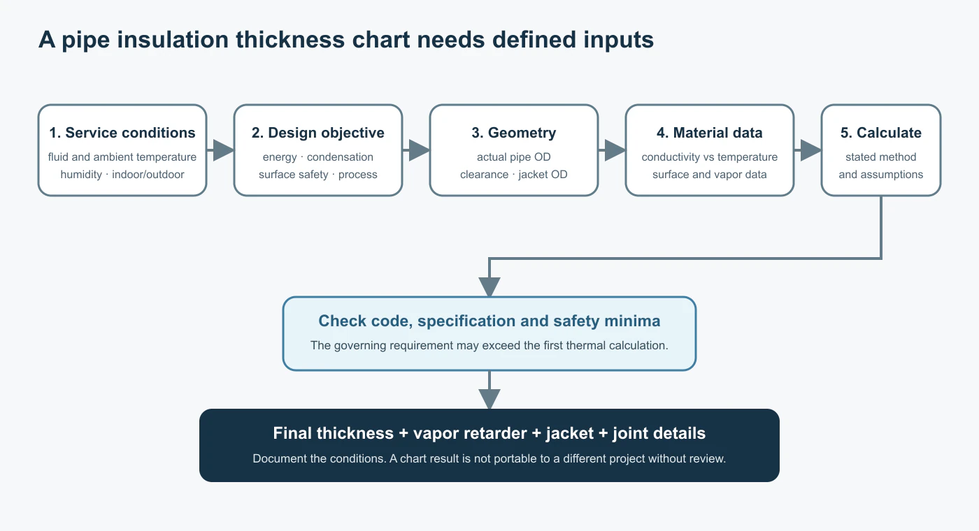
Key selection conditions
- Pipe and service: Actual pipe outside diameter (OD) and fluid operating temperature.
- Environment: Ambient temperature, humidity, and indoor or outdoor exposure.
- Design objective: Heat-loss control, surface-temperature limits, condensation prevention, or freeze-delay criteria.
Pipe Insulation Thickness Reference Table
Based on the energy-efficiency provisions of ASHRAE 90.1-2016, this pipe insulation thickness chart compares approximate insulation thicknesses for NPS ¾, NPS 2, and NPS 6 piping at different fluid temperatures.
| Fluid temperature | NPS ¾ | NPS 2 | NPS 6 |
|---|---|---|---|
| Below 4°C — cold piping | 13 mm | 25 mm | 25 mm |
| 4–16°C — chilled-water or refrigeration piping | 13 mm | 25 mm | 25 mm |
| 41–60°C — hot-water piping | 25 mm | 38 mm | 38 mm |
| 61–93°C — heating and hot-water piping | 38 mm | 51 mm | 51 mm |
| 94–121°C — higher-temperature hot-water piping | 64 mm | 64 mm | 76 mm |
| 122–177°C — high-temperature process piping | 76 mm | 114 mm | 114 mm |
How to read the chart
- Units: These are approximate metric conversions of inch-based reference values. The 13, 25, 38, 51, 64, 76, and 114 mm entries correspond to approximately ½, 1, 1½, 2, 2½, 3, and 4½ in., respectively.
- Pipe size: NPS is nominal pipe size, not actual OD. Standard steel pipe outside diameters for NPS ¾, NPS 2, and NPS 6 are approximately 26.7, 60.3, and 168.3 mm, respectively.
- Thermal conductivity: The reference conditions differ by temperature band. For example, the 4–16°C band uses approximately 0.030–0.039 W/(m·K) at a mean temperature near 24°C; the 61–93°C band uses approximately 0.036–0.042 W/(m·K) at a mean temperature near 52°C. Check the selected material's conductivity at the mean temperature relevant to its service.
- Temperature-band gap: The 17–40°C range is not listed because ASHRAE 90.1-2016 includes an insulation exception for piping conveying fluids with design operating temperatures from 60°F to 105°F (approximately 15.6–40.6°C). This exception is limited to the standard's applicable scope; condensation, safety, and project-specific requirements may still call for insulation.
- Design limits: The pipe insulation thickness chart reflects energy-efficiency reference conditions. Condensation prevention, personnel protection, other applicable codes, or project specifications may require a different thickness. Confirm the relevant code edition and insulation properties before final selection.
How to Use a Pipe Insulation Thickness Chart for Different Pipe Conditions
Hot-Water and Heating Pipes
Consider an NPS 2 steel pipe carrying water at approximately 55°C. With an actual OD of about 60.3 mm, the pipe insulation thickness chart gives a reference thickness of roughly 38 mm for the 41–60°C band. A 40 mm insulation product is a practical size to assess first, provided its thermal properties meet the applicable reference conditions.
As operating temperature rises, the thermal conductivity of the selected insulation can change with its mean temperature. The same thickness may therefore deliver different heat-loss performance across materials or systems.
Where personnel may touch the pipework, an external surface-temperature limit can impose an additional design requirement. Include ambient temperature, airflow, cladding, and surface heat-transfer conditions when checking this limit. Select a thickness that meets both the energy and contact-protection requirements, not only the value shown in the pipe insulation thickness chart.
Chilled-Water and Air-Conditioning Pipes
For an NPS 2 chilled-water pipe operating near 7°C, the pipe insulation thickness chart shows approximately 25 mm. That reference value does not by itself establish whether the system will remain condensation-free in a humid plant room, ceiling void, or other damp location.
The design must account for the ambient dew-point temperature. To control condensation, the insulation's outer surface must remain above the design dew point, and the system must incorporate effective, continuous vapor-retarding protection where required.
Longitudinal seams, joints between sections, elbows, valves, and supports need particular attention. Greater nominal thickness cannot compensate for gaps or discontinuities in the vapor-retarding system. Both closed-cell elastomeric insulation and suitably protected fibrous pipe sections may be considered within their respective service limits; the specific product options are described below.
For joint and vapor-control details, see Pipe Insulation Vapor Barrier.
Outdoor and High-Temperature Industrial Pipes
Outdoor lines require assessment of heat loss alongside wind, rain, ambient temperature, and the protection provided by the external finish. Where water pipes are exposed to freezing conditions, insulation delays heat loss but does not eliminate the risk of freezing. Exposure duration, water volume, flow, and any heat tracing affect the outcome.
High-temperature process piping adds requirements for continuous-service temperature capability, appropriate outer protection, and insulation-grade selection. For these applications, a pipe insulation thickness chart establishes only a preliminary dimensional reference; the material must also withstand the operating conditions. Product temperature ratings and the complete protective system should be checked before deciding on the insulation form.
Insulation Thickness, Pipe Diameter, and Finished Outside Diameter
Thickness is only one dimension needed for product selection. Pipe-section or foam-tube inside diameter must fit the pipe's actual OD, while the completed insulation diameter must fit the available installation space. For a steel pipe with an OD of 60.3 mm, the resulting dimensions are:
| Insulation thickness | Outside diameter after insulation |
|---|---|
| 25 mm | 110.3 mm |
| 40 mm | 140.3 mm |
| 50 mm | 160.3 mm |
| 75 mm | 210.3 mm |
Finished outside diameter = actual pipe outside diameter + 2 × insulation thickness
This dimension affects pipe-to-pipe clearance, supports, wall sleeves, and space for any external cladding. The calculated figures above exclude any additional cladding thickness.
A pipe insulation thickness chart identifies the nominal insulation layer, but the product's inside diameter must still match the actual pipe. Steel, copper, and plastic piping can use similar nominal size descriptions while having different outside diameters.
For further size relationships, see Pipe Insulation Sizing Chart. For projects based on a thermal-resistance target, see Pipe Insulation R-Value.
From Reference Thickness to Available Insulation Products
Once the pipe insulation thickness chart has established a working thickness, match that requirement to the insulation's service temperature, available inside diameter, and installation conditions. Insulvora supplies elastomeric foam tubes, glass wool pipe sections, and rock wool pipe sections for different piping applications.
Closed-Cell Elastomeric Foam Tubes
Closed-cell NBR/PVC elastomeric foam tubes are suitable for chilled-water, air-conditioning, and hot- or cold-water services within the product's specified operating-temperature range. Their closed-cell structure supports condensation-control system design when seams and fittings are properly sealed.
Slit Rubber Foam Pipe has a longitudinal slit for fitting around new or existing pipework. Listed thickness options include 15, 20, 25, 30, 40, and 50 mm, with different inside-diameter combinations. Select the specific combination against actual pipe OD and the required pipe insulation thickness chart reference.
Glass Wool Pipe Sections
Preformed glass wool sections provide a defined insulation layer around straight pipe runs used in hot-water, heating, and mechanical services within the selected product's temperature rating.
Glass Wool Pipe Insulation is available in thicknesses of 25–100 mm and inside diameters of 22–720 mm. Glass wool can also be considered for cold services when a complete and continuous vapor-retarding system is included. Confirm thermal properties and the intended service temperature before selecting the grade.
Rock Wool Pipe Sections
Rock wool pipe sections serve higher-temperature industrial piping, district heating, and mechanical lines where greater insulation thickness may be needed.
Rock Wool Pipe covers thicknesses of 20–150 mm and inside diameters of 22–910 mm. At elevated temperatures, the installation may require suitable supports, metal cladding, and appropriately detailed joints. Thick systems can use multiple insulation layers with staggered seams to reduce continuous gaps through the insulation.
The pipe insulation thickness chart gives an initial thickness target; available thickness-and-inside-diameter combinations must be confirmed for the specific product and operating conditions.
When Is a Pipe Insulation Thickness Chart Not Enough?
A detailed heat-transfer assessment is appropriate when the project specifies a maximum heat loss per metre, a particular external surface temperature, or a condensation-control target. These requirements cannot always be resolved by selecting a nominal value from the pipe insulation thickness chart.
Unlike a flat insulation layer, pipe insulation forms a cylinder. Heat flow per unit length depends on actual pipe diameter, insulation thickness, and thermal conductivity at the relevant mean temperature. Ambient conditions and external surface heat transfer also influence the result.
For example, two hot-water pipes operating at the same temperature can have different heat losses per metre if their diameters differ, even when the insulation thickness is the same. Calculation methods covered by ASTM C680 can be used to compare thickness options for specified heat-loss or surface-temperature conditions, including condensation-related evaluation where applicable.
Use the calculation result to evaluate product options and choose an appropriate available thickness. A pipe insulation thickness chart remains a reference tool rather than a substitute for a project-specific thermal assessment.
Confirm Your Pipe Insulation Thickness and Product Specifications
Share the pipe size or actual outside diameter, fluid operating temperature, service environment, and any required thickness or project criteria already specified. Insulvora can discuss suitable elastomeric foam tubes, glass wool pipe sections, or rock wool pipe sections, confirm the relevant available size combinations, and review quotation requirements.