
Pipe Insulation Sizing Chart: Pipe OD, Insulation ID & Finished OD
A pipe insulation sizing chart helps match the actual outside diameter (OD) of a pipe to the nominal inside diameter (ID) of an insulation product and the required wall thickness. Nominal pipe size alone is not enough: steel and copper pipes with the same inch designation can have different outside diameters and require different insulation bores.
For example, a 2 in NPS steel pipe has an actual OD of 60.3 mm. A 61 mm reference bore in a preformed mineral-fiber shell gives an approximate insulation OD of 111 mm with a 25 mm wall, or 161 mm with a 50 mm wall. These figures describe the insulation layer before any external jacketing is added.
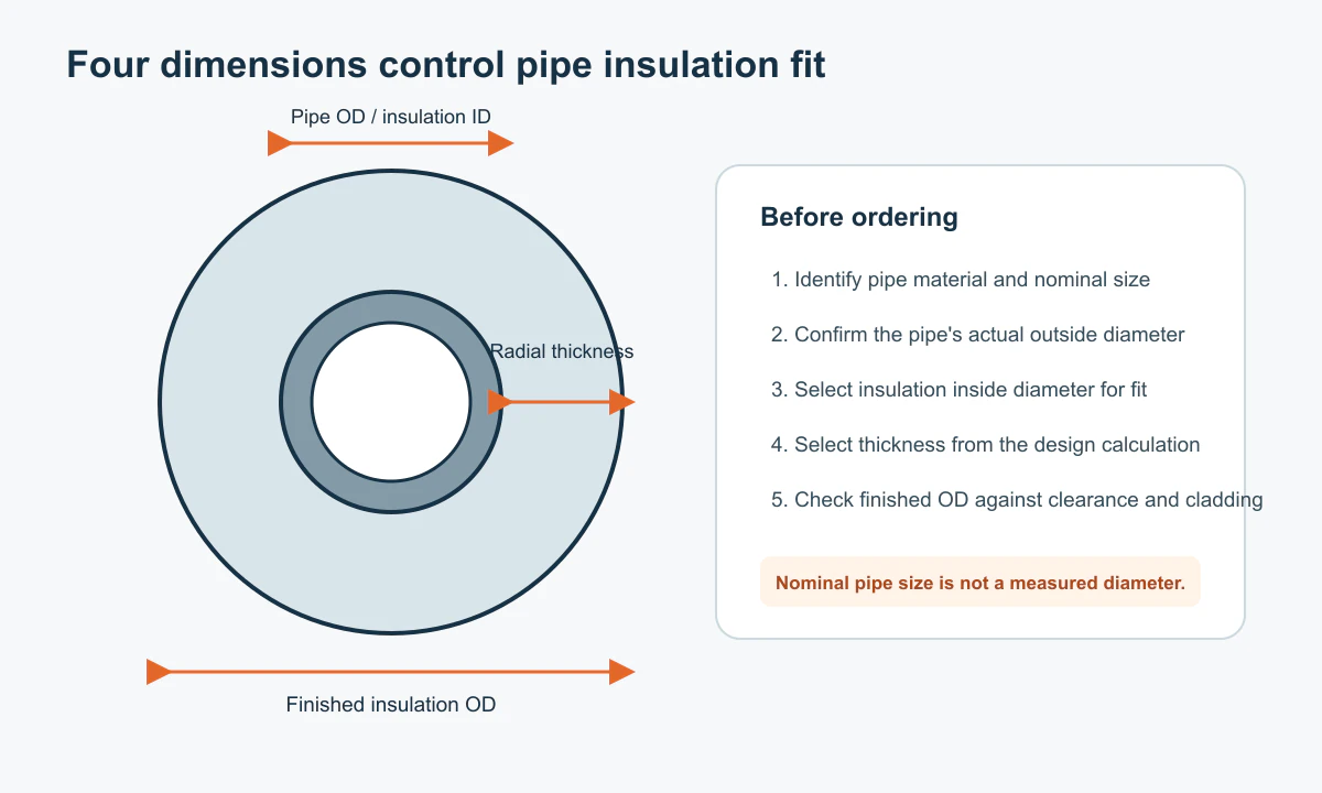
Dimensions to confirm before specifying insulation
- Pipe OD Verify the actual outside diameter under the applicable pipe standard or by measurement.
- Insulation ID Match the product's nominal bore and fit tolerances to that pipe OD.
- Wall thickness Select the required radial insulation thickness for the service and project conditions.
- Insulation OD and installation envelope Calculate the approximate outside diameter of the insulation, then allow separately for jacketing, fittings, and installation clearances.
A 2 in ASTM B88 copper tube, by contrast, has an actual OD of 53.98 mm and a reference insulation bore of 55 mm. It cannot be sized from the steel-pipe table simply because both pipes are described as 2 in. Use the separate steel and copper tables below to identify the appropriate dimensional reference.
NPS Steel Pipe Insulation Sizing Chart
NPS is a nominal designation, not a direct measurement in inches. The actual steel-pipe OD follows the applicable dimensional standard. The pipe insulation sizing chart below lists common NPS pipe ODs, reference IDs for preformed mineral-fiber shells, and calculated insulation ODs for 25, 50, and 75 mm wall thicknesses.
| NPS | Actual pipe OD (mm) | Reference insulation ID (mm) | OD at 25 mm wall (mm) | OD at 50 mm wall (mm) | OD at 75 mm wall (mm) |
|---|---|---|---|---|---|
| ½ in | 21.3 | 22 | 72 | 122 | 172 |
| ¾ in | 26.7 | 27 | 77 | 127 | 177 |
| 1 in | 33.4 | 34 | 84 | 134 | 184 |
| 1¼ in | 42.2 | 43 | 93 | 143 | 193 |
| 1½ in | 48.3 | 49 | 99 | 149 | 199 |
| 2 in | 60.3 | 61 | 111 | 161 | 211 |
| 2½ in | 73.0 | 74 | 124 | 174 | 224 |
| 3 in | 88.9 | 90 | 140 | 190 | 240 |
| 4 in | 114.3 | 115 | 165 | 215 | 265 |
| 5 in | 141.3 | 143 | 193 | 243 | 293 |
| 6 in | 168.3 | 170 | 220 | 270 | 320 |
| 8 in | 219.1 | 221 | 271 | 321 | 371 |
| 10 in | 273.1 | 275 | 325 | 375 | 425 |
| 12 in | 323.9 | 326 | 376 | 426 | 476 |
All dimensions are in millimeters. Reference insulation IDs in this pipe insulation sizing chart follow a common preformed mineral-fiber sizing system; they are not universal product bore sizes. Calculated ODs use the reference ID and nominal wall thickness, excluding jacketing and manufacturing tolerances. Confirm the dimensions of the selected product series.
For a 4 in NPS steel pipe, the actual OD is 114.3 mm, not 101.6 mm (4 × 25.4). A shell with a 115 mm reference ID and a 50 mm wall has an approximate insulation OD of 215 mm . This is a useful initial dimension for pipe-rack spacing and penetrations; the installed envelope may be larger once protective covering and other clearances are considered.
ASTM B88 Copper Pipe Insulation Sizing Chart
ASTM B88 copper water tubing uses a different nominal-size convention from NPS steel pipe. A nominal 1 in copper tube has an actual OD of 28.58 mm, compared with 33.4 mm for a 1 in NPS steel pipe. Use the copper-specific pipe insulation sizing chart when identifying a reference bore for these tubes.
| Nominal copper tube size | Actual tube OD (mm) | Reference insulation ID (mm) | OD at 25 mm wall (mm) | OD at 50 mm wall (mm) | OD at 75 mm wall (mm) |
|---|---|---|---|---|---|
| ½ in | 15.88 | 16 | 66 | 116 | 166 |
| ¾ in | 22.23 | 23 | 73 | 123 | 173 |
| 1 in | 28.58 | 29 | 79 | 129 | 179 |
| 1¼ in | 34.93 | 35 | 85 | 135 | 185 |
| 1½ in | 41.28 | 42 | 92 | 142 | 192 |
| 2 in | 53.98 | 55 | 105 | 155 | 205 |
The reference IDs in this pipe insulation sizing chart apply to the corresponding preformed sizing system, not every insulation product. Calculated insulation ODs exclude jacketing.
Refrigeration copper tubing, PEX, PPR, and other plastic pipe systems may follow different dimensional standards. Confirm the actual OD of the specified series before selecting an insulation bore. For related applications, see Copper Pipe Insulation and PEX Pipe Insulation .
How to Use a Pipe Insulation Sizing Chart for OD, ID, and Clearance
Pipe OD is the outside diameter of the bare pipe or tube. It determines the starting dimension for a correctly fitting insulation bore.
Insulation ID is the nominal inside diameter of the insulation product. Preformed glass-wool and rock-wool shells use specified bore series, with fit and manufacturing tolerances that must be confirmed for the selected product.
Insulation wall thickness is measured radially. It changes the outside diameter of the insulated pipe and is selected to meet the operating temperature, ambient conditions, material properties, and other project requirements—not simply the pipe size.
For a preformed shell, the pipe insulation sizing chart uses this approximate relationship:
Insulation OD ≈ nominal insulation ID + 2 × insulation wall thickness
If the insulation ID has not been chosen, pipe OD + 2 × wall thickness gives a simplified estimate for a close-fitting insulation layer. The result can differ from the reference-ID calculation because the insulation bore and the pipe OD are not necessarily identical.
The calculated insulation OD is not necessarily the final installed outside diameter. Metal jacketing, covering overlaps, fabrication allowances, and installation tolerances can increase the envelope. When checking space between parallel insulated lines or through walls, above ceilings, in plant rooms, and along pipe racks, consider those additions. Bends, flanges, valves, supports, and removable covers may need more room than a straight insulated section.
The values in a pipe insulation sizing chart are suitable for preliminary dimensional planning. For closely spaced installations or jacketing fabrication, check the actual product dimensions and protection-system details. For thermal thickness selection, refer to the Pipe Insulation Thickness Chart .
Insulation Bore Ranges by Product Form
Reference bore values in a pipe insulation sizing chart must be checked against the selected insulation material and product series. Insulvora supplies preformed glass-wool and rock-wool pipe sections and flexible rubber-foam pipe insulation. Their available sizes and fitting behavior differ.
Glass Wool Pipe Insulation for Mechanical Pipework
Glass Wool Pipe Insulation is supplied in preformed sections for mechanical and industrial pipework, subject to the product's operating-temperature and system requirements.
- Insulation ID range: 22–720 mm
- Wall thickness: 25–100 mm
- Section length: 1 m
These dimensions provide options for matching the pipe OD to a formed shell and the specified wall thickness. Confirm the required bore and available dimensions for the chosen series.
Rock Wool Pipe Insulation for Industrial Services
Rock Wool Pipe is a preformed option for industrial and mechanical pipelines requiring higher-temperature capability or greater insulation thickness, within the selected product's limits.
- Insulation ID range: 22–910 mm
- Wall thickness: 20–150 mm
- Section length: 1 m
For steam and other hot-service pipelines, account for operating temperature, insulation design, and external protection when choosing the shell. The size range may accommodate larger pipe diameters or thicker systems, while fittings and cladding still require separate dimensional checks.
Slit Rubber Foam Pipe Insulation for HVAC and Water Lines
Slit Rubber Foam Pipe is a closed-cell NBR/PVC foam product with a longitudinal slit for suitable air-conditioning, chilled-water, and other service pipes.
Available wall thicknesses include 15, 20, 25, 30, 40, and 50 mm . Bore availability varies by thickness. For the 25 mm wall series, listed nominal IDs are 20 / 25 / 32 / 43 / 48 / 60 mm .
For a 2 in NPS pipe with a 60.3 mm OD, the 60 mm nominal-bore rubber-foam option should be checked for fit. Unlike a preformed mineral-fiber shell with a 61 mm reference ID, flexible rubber foam has different fitting behavior. The nominal bore, flexibility, manufacturing tolerance, and seam closure must all be considered.
For chilled-water and refrigerant lines below ambient temperature, a suitable fit and properly sealed joints help maintain insulation continuity and condensation control. The mineral-fiber reference IDs in the tables above do not represent the available rubber-foam bore series.
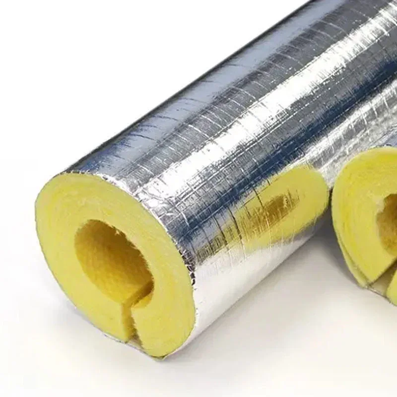
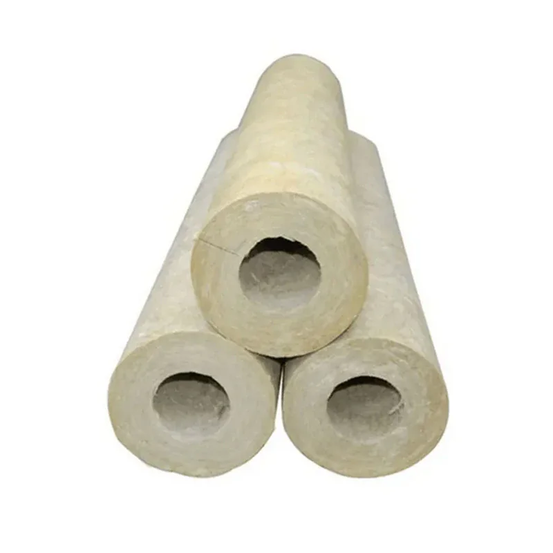
Preformed glass-wool and rock-wool pipe insulation sections.
Using a Pipe Insulation Sizing Chart for Existing Pipes
When drawings are incomplete or the work involves replacing existing insulation, measure a representative exposed straight section of pipe. Avoid flanges, sockets, fittings, and visibly distorted areas. If coatings, heat tracing, or other components will remain beneath the insulation, account for their combined outside dimensions.
If the pipe circumference can be measured but direct access to the diameter is limited, use:
Actual pipe OD = measured outside circumference ÷ π
For example, a bare-pipe circumference of approximately 189.4 mm corresponds to an OD of about 60.3 mm, consistent with a 2 in NPS steel pipe. The pipe insulation sizing chart can then be used to identify a reference bore for further product checks.
Measuring around old insulation gives the outside size of the existing assembly, not the bare pipe OD. For replacement projects, also examine surface condition, supports, bends, valves, and penetrations that may affect installation of new sections.
Turning a Pipe Insulation Sizing Chart into a Product Specification
A purchasing specification should connect the actual pipe dimension to the insulation material, nominal bore, wall thickness, and relevant installation conditions. The example below illustrates a preformed rock-wool pipe shell for a 2 in NPS steel pipe.
| Specification item | Example |
|---|---|
| Pipe type | NPS steel pipe |
| Nominal size | 2 in |
| Actual pipe OD | 60.3 mm |
| Insulation material | Preformed rock-wool pipe shell |
| Reference insulation ID | 61 mm |
| Insulation wall thickness | 50 mm |
| Approximate insulation OD | 161 mm |
| Section length | 1 m |
| External protection | To suit installation conditions |
A pipe insulation sizing chart provides a dimensional starting point, not a universal finished-product specification. If the installation also requires a vapor barrier, jacketing, elbows, support details, or technical documentation, see Pipe Insulation Specification for broader system considerations.
Request Pipe Insulation in the Right Size
After consulting the pipe insulation sizing chart, share the pipe type or dimensional standard, nominal size or actual OD, preferred insulation material, and required wall thickness. With those details, Insulvora can review suitable sizes for glass-wool, rock-wool, or rubber-foam pipe insulation and confirm product dimensions and pricing according to the requested requirements.